Correct Ultrasound Sensor Placement for Better Failure Detection
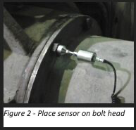
Ultrasound signals are ideal for condition monitoring due to their boundary behavior, which isolates them to their source. For accurate data, place the sensor on a bolt head directly connected to the gearbox housing, rather than on the gearbox cover.
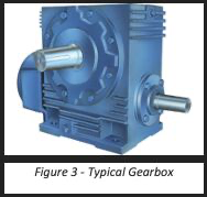
Correct Sensor Placement for Collecting Data on a Gearbox
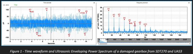
A good way to assess the health of gears is to collect a DYNAMIC ultrasound signal. You want to capture at least three, and preferably more, complete revolutions of the gearbox. Analysis is straightforward. Use UAS3 software to view the signal in the time waveform and spectrum displays. Use the software’s many analysis tools to determine the exact defect. Just remember that good quality data is essential, sensor placement is important, and identifying boundary behaviors a key for success.
Sound has Boundaries
Think of ultrasound as the silent introvert. It likes to stay where it is and doesn’t mix well with other ultrasound from other media. We call this “boundary behavior” and it’s another characteristic that makes ultrasound such an attractive condition monitoring technology. Ultrasound signals remain isolated to their source, making it easy to pinpoint defects without interference from other elements of the machine.
Sensor Placement
Inspectors tempted to place their ultrasound sensor directly on the gearbox cover, should reconsider. This common mistake affects data integrity. A gasket seals the cover plate to the gearbox housing. The specific acoustic impedance of the gasket material differs greatly from the cast metal of the gearbox. The change in materials is a boundary barrier through which bashful ultrasound is reluctant to pass. A better option is to place the sensor on a bolt head, which is directly connected to the gearbox housing. The result is the capture of crystal clear ultrasound signals for listening, trending, and condition assessment.
Additional Images