Ground Loops: What is causing that electrical noise
Electrical noise at 60 or 50 Hertz in data may be caused by ground loops, where the measurement system and sensors are grounded at multiple points. To avoid ground loops, isolate sensors from the test structure using isolation pads or disconnect one ground path.
Ground Loops
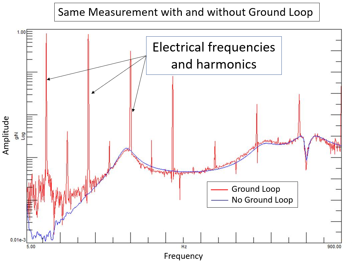
Question: Why does my data have 60 Hertz (or 50 Hertz) peaks and harmonics (Figure 1)?
Answer: Congratulations! You might have a “ground loop”!
Background
The electricity in a wall outlet operates at 60 Hertz (in the United States) or 50 Hertz (in Europe). If your measurement system and transducers are not properly isolated from electrical power sources, these frequencies can contaminate the measurement data.
For example, electrical contamination can be caused by electromagnetic interference when a power cable is laying close to an accelerometer cable. Or fluorescent lights might induce electrostatic interference on poorly isolated wires.
But another cause is something called a “ground loop”. In a ground loop, the measurement system and sensors are grounded at multiple points. Because there is more than one ground point, electrical disturbances can flow between the two grounds and contaminate the measurement signals with electrical noise.
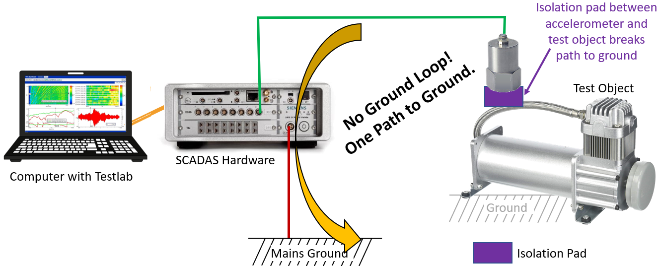
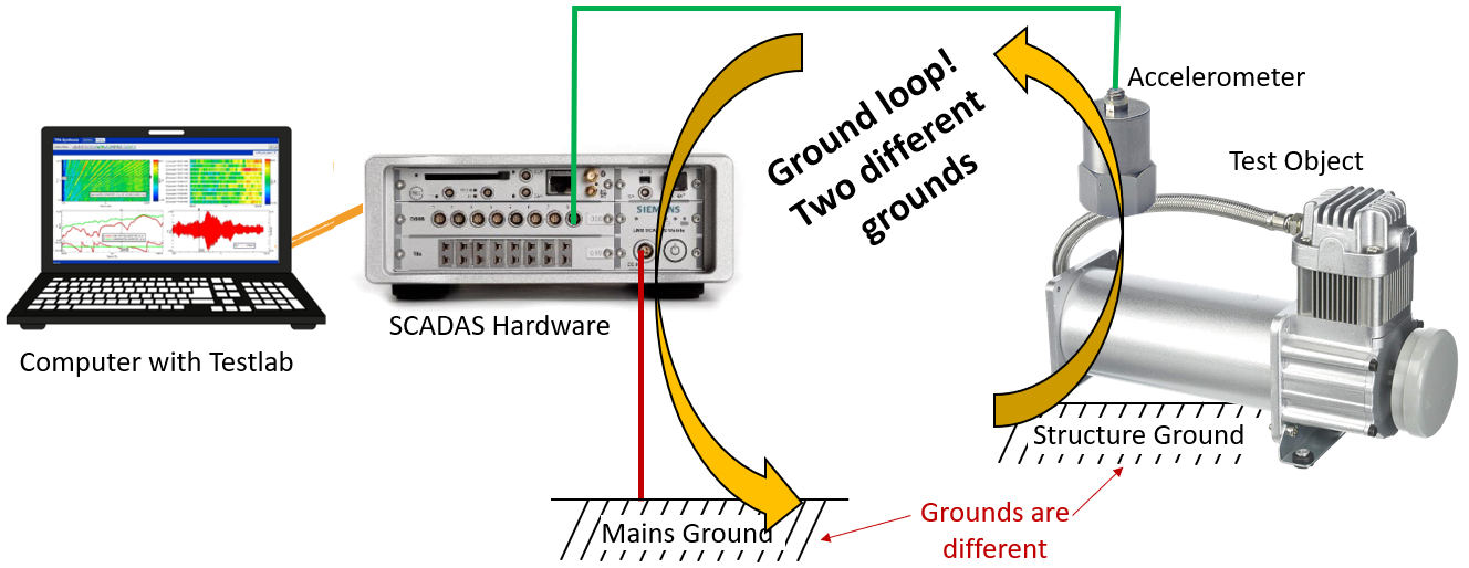
An example of a ground loop is shown in Figure 2.
The measurement and sensor system has two paths to ground:
The accelerometer sensor has direct metal to metal contact with the grounded test object. This allows electricity to flow to and from the structure ground.
The SCADAS frontend is plugged into ground of the electrical mains power (ie, the wall outlet).
To avoid the ground loop, one of the paths must be disconnected from ground. There should only be one path to ground for the entire system.
What can be done?
There are two things that can be done (in order of importance) to avoid a ground loop:
Isolate Sensors
Isolate Measurement System
Isolate Sensors
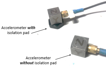
The best solution is make sure the sensors are isolated from the test structure, so that there is no possibility of electrical flow between them. This can be done by inserting an isolation pad between the test object and accelerometer as shown in Figure 3.
Troubleshooting a Ground Loop
Note that troubleshooting such a ground loop can be difficult.
For example, if using bee’s wax material to mount the accelerometer on the test structure, depending on how tightly the accelerometer is pressed, the bee’s wax might provide a certain degree of isolation (light pressure), or no isolation (pressed firmly). This can be puzzling as the electrical noise can “come and go” over the time duration of a test.
Even the number of accelerometers can be key – the more accelerometers directly mounted on the test structure, the better the grounding and electrical flow.
Hopefully, this article gives some overall guidance on how to recognize this issue and troubleshoot it.
More detail in the source link
Additional Images